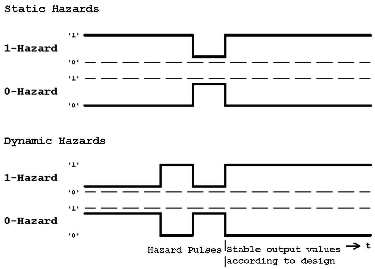
Figure 5.5: Hazard Classification.
| Contents | Previous Chapter | Next Chapter |
The reason for hazards that occur on the output of combinational circuits lies in the structure of the circuit realization. For the occurrence of spurious pulses different reasons can be responsible. Consequently the effort that is required for their removal can be quite diverse.
Referring to their causes (and removal options), hazards can be distinguished in:
Referring to their behaviour, hazards can furthermore be categorized in:
Figure 5.5: Hazard Classification.
5.2.1 Logic Hazards
Definition of Logic Hazards:
Signal changes of this type are called "single-component transitions".
For such a hazard to occur three conditions must be fulfilled:
The first two prerequisites are almost always fulfilled in a combinational circuit, time delayed signals are joined accordingly for instance at an OR gate or an AND gate, so that static hazards can occur:
Figure 5.6: Formation of Hazards.
In most cases a static 1-hazard occurs at an OR-gate. Because of the propagation delay and the signal switching relation in the example (see above), the input signals x0 and x1 will for a short time assume simultaneously the value '0'. This causes a 1-Hazard (y0 = 0). In this case the hazard could be avoided adding an additional term x0·x2, that will remain stable at '1' during the single-component transition and thus guarantee the function value '1'.
Similarly a static 0-hazard will occur at an AND-gate (see above) when the change to '0' of input signal x0 will be delayed relative to the corresponding edge of x1. Again this can be corrected with an additional common term ![]() ,
that will remain at the stable value '0' during the single-component transition.
,
that will remain at the stable value '0' during the single-component transition.
In the first example the logic hazard can be removed using an additional gate that realizes the term x0·x2.
As can be seen from the K-Map (below) this logically redundant term corresponds to an absolutely eliminable prime implicant.
For the hazard-free combinational circuit of the example follows:
Figure 5.7: Building a hazard-free combinational circuit.
Figure 5.8: K-Map with the additional term x0·x2

Figure 5.9: Combinational circuit in OR/AND form (with additional OR-gate for hazard avoidance).
As can be seen, the circuit implemented this way now contains a 0-hazard in case of a single-component transition
 '0'
'0'
when at the same time the other input values remain constant x0 = x2 = '0':
Figure 5.10: Timing Diagram.
Also in this case the hazard can be removed introducing a logically redundant gate. Again the required term
![]() corresponds to an absolutely eliminable prime implicant (see K-Map Fig. 5.11).
corresponds to an absolutely eliminable prime implicant (see K-Map Fig. 5.11).
Figure 5.11: K-Map with the additional term ![]()
Boolean function (CNF) with additional term:
Logic hazards can always be removed by a modification of the circuit structure. To avoid logic hazards the circuit realization of all prime implicants (including the eliminable one) is sufficient.
Definition of Functional Hazards:
Signal changes of this type are called "Multi-Component Transitions".
From the example circuit used above it can be seen that because of the mode of operation this type of hazards can easily occur.
Even when logic hazards are already removed, simultaneous transitions
'0' and x2: '0' '1'or the inverse switching transitions will lead to a hazard.
This situation can be observed in the K-Map:
Figure 5.12: K-Map with functional Hazard.
When the real transition follows path (1) the value '0' will be output for a short time reflecting the definition of the function. When the transition follows path (2) on the other hand no functional hazard will occur, because obviously a changing function value is not produced in this case.
In other words, functional hazards are the property of Boolean Functions and therefore of the corresponding circuits.
To prevent the functional hazards the responsible multi-component transition has to be split into a series of single-component transitions, so that a change of the function values cannot occur anymore. Obviously these single-component transitions have to be free of logic hazards.
But these measures will usually strongly slow down the circuit operation. In that case a work around is only possible using synchronous circuits instead.
Dynamic Hazards are produced by static hazards that occur immediately before the change of an output signal. Therefore they have two causes:
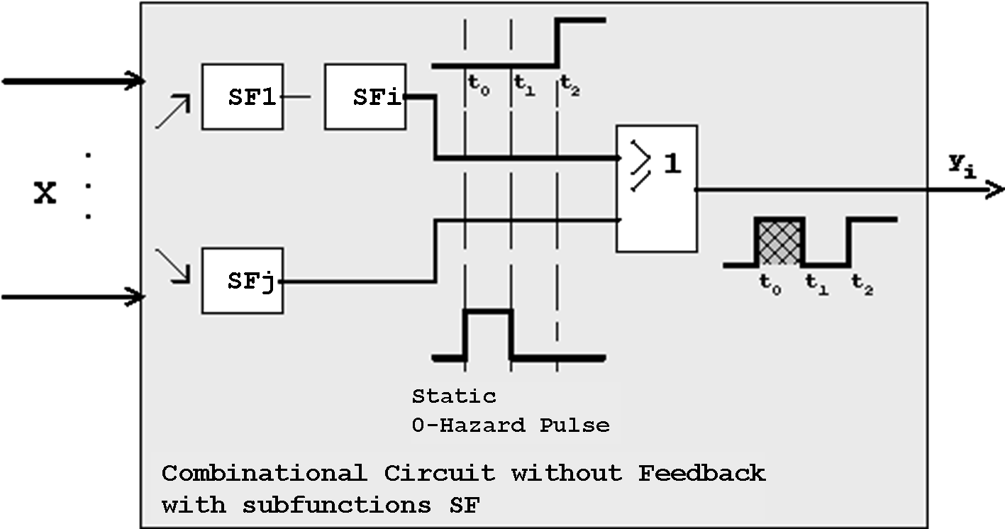
Figure 5.13: Occurrence of a dynamic 1-Hazard Pulse.
These dynamic hazards can only be prevented when the causal logic hazards are removed.
Example of a circuit with dynamic hazard:
As an example of a circuit with dynamic hazard the following Boolean Function shall be realized:
The following circuit corresponds to this Boolean Function:
Figure 5.14: Circuit with dynamic Hazard.
The related timing diagram examines the temporal development of the involved signals. It can be clearly seen that the output signal
y0 will initially assume the new level '1'. But because of the static 1-hazard that occurs at the intermediate signal 4, a low signal is produced for the duration of one gate delay. Obviously this dynamic 1-hazard can only be prevented through removal of the causal static hazard.
Figure 5.15: Timing Diagram
| Contents | Previous Chapter | Next Chapter |