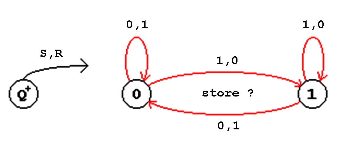
Figure 4.12: State Transition Diagram of the RS FF.
| Contents | Previous Chapter | Next Chapter |
The Latch Flip-Flop was introduced in order to define the basic properties of a flip-flop. But is does not really represent a device which is relevant for any application.
Characteristic for the basic flip-flop is the bistable behaviour, i.e. the existence of two distinguishable states that can be represented by logical values "0" and "1".
The two actions that are used to program these FF values are called "Set" and "Reset" function, respectively. Additionally it is possible to "Store" the programmed value.
The two states "reset"
and "set" are abbreviated as R- and S-state, respectively. The corresponding basic FF is called the RS Flip-Flop.
This RF-FF corresponds to the beforehand introduced Flip-Flop properties, only the also demanded edge-triggering is not available.
The three functions of the RF Flip-Flop can again be described objectively using a function (truth) table and a state transition diagram:
| Set | |||
| Reset | |||
| Store |
Table 4.3: Function Table of the RS FF.
Figure 4.12: State Transition Diagram of the RS FF.
When an implementation of the RS FF in NOR or NAND form, respectively, is pursued, the following basic basic forms can be used:
Figure 4.13: Basic Forms of the RS Flip-Flop.
The feedback signal is dominant, so that the required store function is ensured:
Store:
S=R=0 in case of NOR, S=R=1 in case of NAND.
Using the K-Map a practical realization can be found in NOR or NAND form:
| Figure 4.14: K-Map of the RS Flip-Flop. | 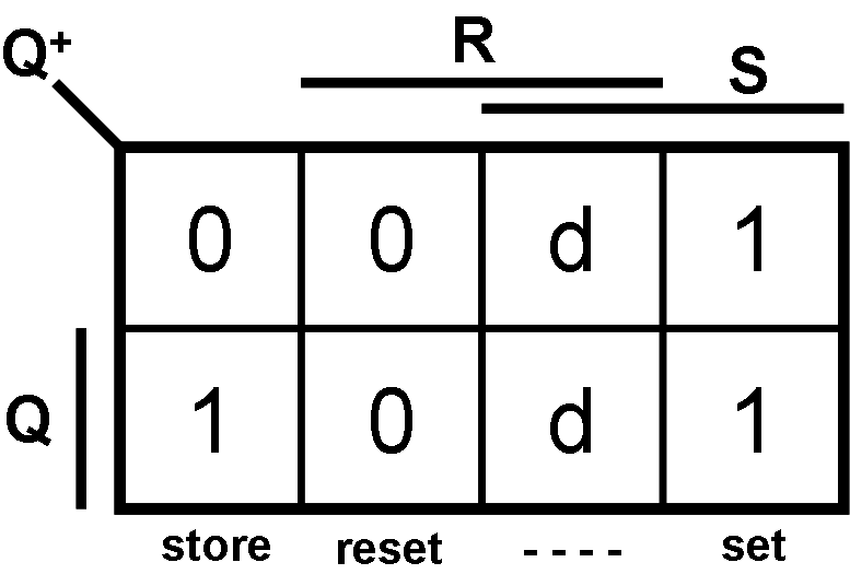 |
When the "don't cares" are interpreted as d=0, then the function will be:
| , | (4.3) |
which leads directly to the NOR-realization of the RS Flip-Flop:
| Figure 4.15: RS Flip-Flop in NOR-Realization. |  |
This standard structure of crossed feedback paths that was found forming implicants in the K-Map is valid for the NOR as well as for the NAND realization.
Therefore the result for the final K-Map of the RS Flip-Flop in NOR structure is:
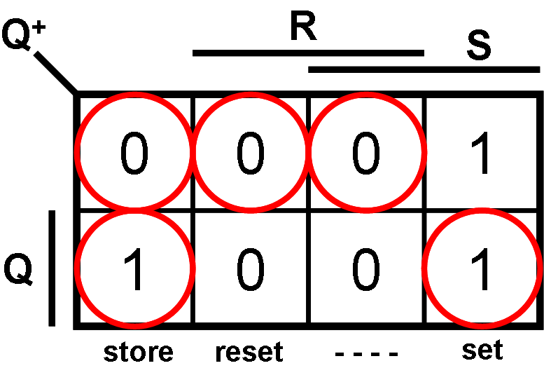
Figure 4.16: K-Map of the RS Flip-Flop in NOR Realization.
Again the circles are marking the stable states..
Note 1:
Note 2:
Because of these two reasons the input configuration R=S="1" is forbidden in the case of the RS-NOR FF. The corresponding rule applies to the RS-NAND FF for the input combination R=S="0".
Summary: RS-Flipflops
Figure 4.17: NOR and NAND Realization of the RS Flip-Flop.
 |
 | |||||
Table 4.4: Function Table of the RS Flip-Flop in NOR- and NAND-Realization.
| Contents | Previous Chapter | Next Chapter |