Figure 4.2: State Definition.
| Contents | Previous Chapter | Next Chapter |
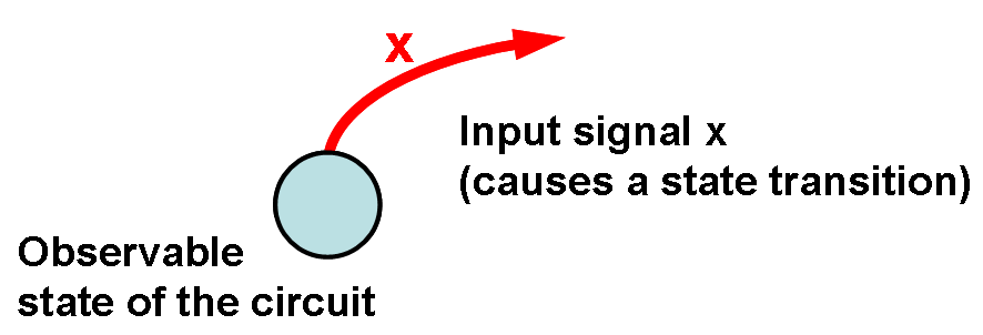
A sequential logic circuit can be described by all its possible states. Transitions between different states can be shown in a graphical presentation using vectors that at the same time define the signal that is necessary for the change of state.
This graphical description of a function is called a state diagram. The following notation applies:
Figure 4.2: State Definition.
This principle will be explained using the example of a Modulo-4 Counter (a detailed description of this binary counter will be given later):
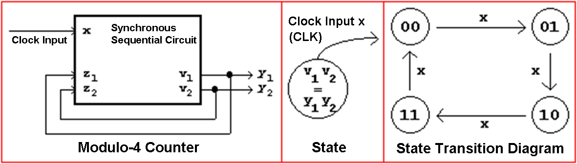
Figure 4.3: Description of the Modulo-4 Counter.
| Contents | Previous Chapter | Next Chapter |