Figure 3.1: Typical Multiplexer-Demultiplexer Application.
| Contents | Previous Chapter | Next Chapter |
In chapter 2 the multiplexer was introduced in connection with the decomposition of functions. This circuit will now be treated in detail. Especially the application of the demultiplexer (DMUX), which has a complementary function compared to the multiplexer, will be discussed.
A simple data communication example will clarify how the multiplexer and the corresponding demultiplexer are working.
In this example a one-way data communication will be set up between n transmitters (senders) and m receivers. This problem can be solved using the well-known "selection (MUX) and distribution (DEMUX) principle".
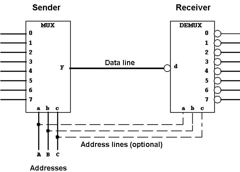
For n=m=8 the following realization is possible:
Figure 3.1: Typical Multiplexer-Demultiplexer Application.
On the side of the sender (transmitter) the multiplexer selects one of the input signal for the transmission. On the receiver side the demultiplexer implements the reverse function, distributing the data to the connected receiver lines.
The procedure shown here can be modified by abandoning the optional address lines. In this case the necessary address information will also be sent over the data lines. To use this mode of operation the receiver address will be sent before the data using a predefined rule (protocol).
The demultiplexer used in this example produces inverted output signals which can be compensated using an equally inverted input. This functional mode has been selected with the similar "decoder" circuit in mind, which will be introduced below. Decoders normally work in what is called "active low" mode.
| Contents | Previous Chapter | Next Chapter |