Figure 2.48: Digital Multiplexer Circuit.
| Contents | Previous Chapter | Next Chapter |
In connection with the Shannon decomposition a "digital switch" was needed. The demand for such a device is met by so-called multiplexer circuits.
Multiplexer are combinational circuits that are available as integrated circuits. They serve as switches for digital signals, but when designed for this purpose they can also be used to switch analog signals.
For its basic function the multiplexer typically needs the following signal lines:

Figure 2.48: Digital Multiplexer Circuit.
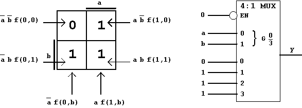
In the most simple case, to implement a Boolean Function using Shannon decomposition, all n function arguments can be connected with the selection inputs si , so that 2n data inputs are selected. In this case each individual data input represents exactly one function value. According to the Shannon decomposition shown above this corresponds to the realization of the OR-function f(a,b) = a + b:

Figure 2.49: Implementing Functions using Multiplexer.
Because the multiplexer used here will connect one out of four input signals with the output y, it is called a
4:1 Multiplexer (short form: "4:1-MUX", or "MPX"). In the same way multiplexers for a higher number of input signals can be defined: 8:1, 16:1, etc.
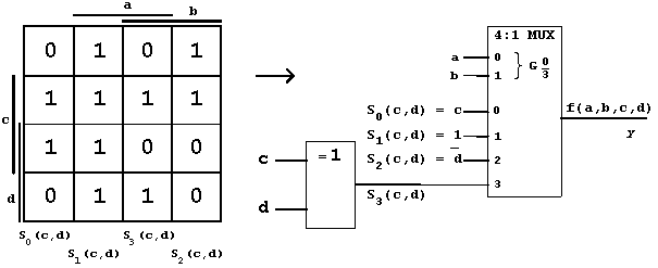
Obviously, the example function described above for which a circuit realization had to be designed, can now be implemented using a multiplexer:

Figure 2.50: Multiplexer realization for Figure 2.46.
The decomposition of this sample function can be continued:
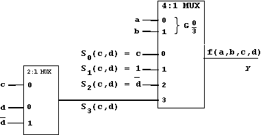
For the remaining function  another Shannon decomposition using multiplexer realization is possible. In this case a 2:1-multiplexer is sufficient.
Thus the structure of a multiplexer tree is created.

Figure 2.51: Complete MPX-Realization for Figure 2.50.