 | 
|
|
 | 
|
|
 | 
|
|
 | 
|
Figure 2.35: Karnaugh Diagrams for Table 2.7 (Code Conversion).
| Contents | Previous Chapter | Next Chapter |
2.9.1 Design of the combinational circuit for a
Code Converter
Combinational circuits can be applied for the conversion of codes. In this example the so-called BCD Code (Binary Coded Decimal) shall be transformed into the Gray Code. For this purpose the Boolean functions and the circuit implementations will be developed and simplified using Karnaugh Diagrams.
Code Definition:
Variable | Variable | |||||||
For each output variable a K-Map has to be constructed and simplified. For this purpose all minterms are entered as '1' values. From the code table can be seen that only 10 from 16 fields are necessary. The BCD Code is limited to the numbers 0 to 9, so that the remaining fields can be freely defined as "don't cares" (indicated by 'd').
Those inputs that are not used in the BCD code are called "Pseudo Decimals" (or sometimes "Pseudo Tetrades").
In the following K-Maps the implicants used for the minimizations and the corresponding DNFs are shown:
|
|
|
|
|
|
|
|
|
|
|
Figure 2.35: Karnaugh Diagrams for Table 2.7 (Code Conversion).
Forming meaningful groups in the corresponding K-Maps as shown above, the following simplified relations are found for the output variables O, P, Q, and R:
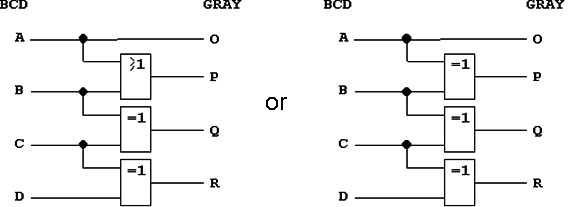
Figure 2.36: Circuit Implementation of the BCD to Gray Code Converter.
Obviously these two circuit implementations are functionally identical, but the second version has the advantage that only one type of gate has to be used (XOR).
a) Segment Selection
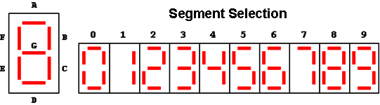
Figure 2.37: Elements of a Seven-Segment Display.
b) Circuit Structure
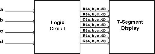
Figure 2.38: Block Diagram of a Seven-Segment Control Circuit.
c) Function Table:
Using the indicated segment selection results directly in the following definition for the 7-bit code:
d) K-Maps:
Figure 2.39: K-Maps for the 7-Segment Control.
| Contents | Previous Chapter | Next Chapter |