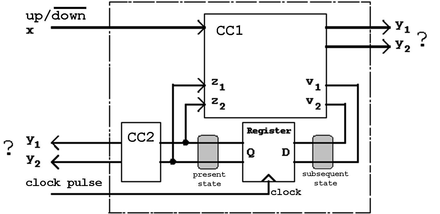
Figure 6.4: Up/Down Counter (Modulo-4).
| Contents | Previous Chapter | Next Chapter |
As has been seen, in a finite state machine the logic of the combinational circuit will be realized using a storage device. Because of this construction FSMs are designed in a fairly elementary and can be modified quite easily. Its treatment is based on the theory of finite automata.
Under the synchronous finte state machines two types are of very special importance: the Mealy Machine and the Moore Machine. They will therefore be covered in more detail.
So far only the states of the FSMs has been treated, nothing has been decided about the outputs.
As an example, the already known modulo-4 counter should be expanded by the addition of an "Up/Down" control input. With this input signal it should be possible to define the counting direction: With '1' applied to the input, the up-count will be selected, otherwise the down-count will be active.
Figure 6.4: Up/Down Counter (Modulo-4).
The counter should be realized in such a away that the following state coding sequence will be fulfilled:
This procedure is called "single-step" coding; with each transistion only a single bit will change. This type of coding has the advantage that function hazards cannot be produced.
Assuming this coding the following state transistion diagram of the counter will be vaild:
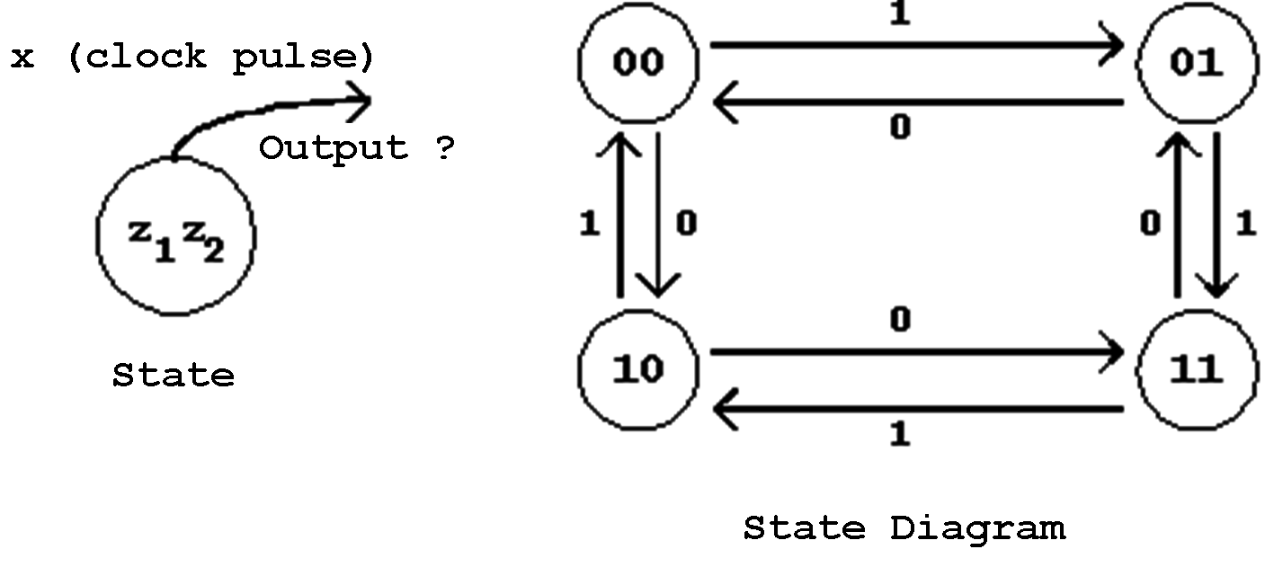
Figure 6.5: State Diagram of the Modulo-4 Counter.
For the finite state machine shown here the terms "present state" and "output" should now be defined in a suitable form.
Definition of the present state:
Only in connection with the synchonous FSMs two alternatives exist for the description of the present state: the feedback outputs as well as the feedback inputs can be used for this purpose.
Obviously it makes more sense to use the stable output values of the register for this purpose, in this case z1 and z2. The new counter value will be assumed with the leading edge of the clock pulse.
Definition of the output:
For the output selection two possibilities exist:
The outputs
yi of the combinational circuit CC1 can be used or the corresponding outputs of CC2.
Certainly the output via
CC2 is more advisable, because in this case the output values cannot be affected by a change at the input x. The output values depend only on the current state determined by z1 und z2.
The finite state machine described in this form is called a Moore Machine (or Moore Automaton, plural Moore Automata). In this case the output is completely determined by the current state, so that the following state diagram is valid for this machine:
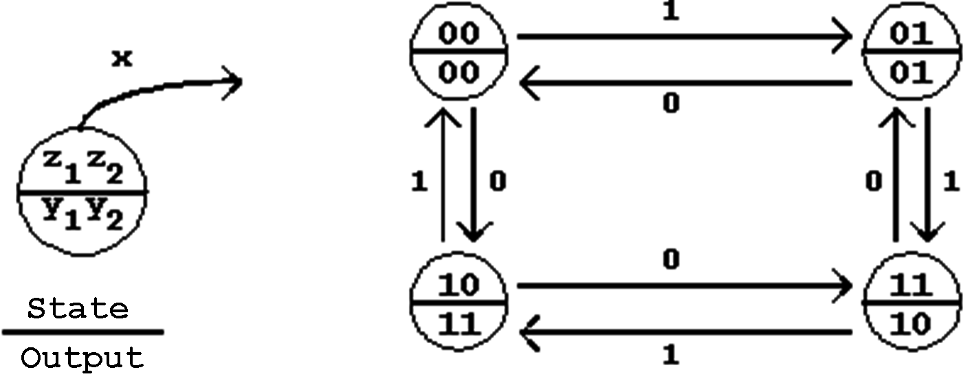
Figure 6.6: State Transition Diagram for the Moore Model.
The state definition has been modified in this presentation, in order to indicate the direct interconnection between the output and the current state.
In case that contrary to the above solution the output via CC1 is chosen, it will be affected immediately by an input change (x).
In this case the resulting finite state machine in referred to as a Mealy Machine (or Mealy Automaton). The corresponding state diagram reflects the modified situation:
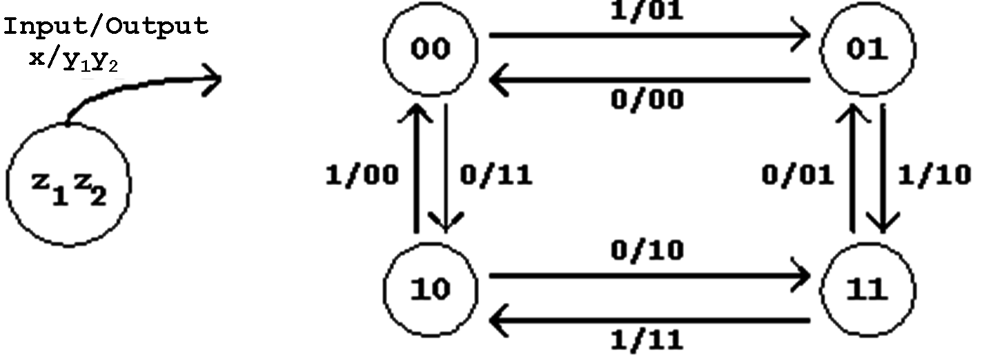
Figure 6.7: State Transition Diagram for the Mealy Model.
In this case, too, the state definition has been chosen in such a way that the dependence of the output on the input becomes visible ("x/y1y2"; this means that y1y2 change with the input variable x).
The difference to the Moore presentation shown above becomes immediately visible when the relation between the change of state and the change of output is further investigated..
Example:
The machine (counter) be in the state '01'. When now the input "x" changes to '1' the result will be as follows:
In summary the difference between the here presented automata can be described as follows:
Moore Notation: In an FSM of type Moore the output will be directly determined only by the current state. A change in the external inputs will change the outputs only with the change of state. The output occurs synchronously.
Mealy-Notation: In an FSM of type Mealy the output depends on the current state as well as directly on the external input. The output occurs asynchronously.
Comparing the corresponding state diagrams, the difference between the automata can be characterized by the fact that in a Mealy machine the output runs ahead of the change of state and such ahead of the Moore machine.
Hint:
Despite the single-step change of state the counter value shall be presented in binary form in the Moore as well as the Mealy mode of operation. Therefore the combinational circuits CC1 and CC2 that are responsible for the outputs have to fulfill the required output function:
Table 6.1: Definition of the output function.
Hint:
Because of its direct dependence on the external input, the use of the combinational circuit (CC1) is always required for a Mealy output.
6.2.2 Mealy and Moore Automata:
Design Principles
The automata model (FSM model) shown here using the example of an Up/Down-Counter can now be presented in a generalized form.
Moore and Mealy Machines can be described using the following basic circuits:
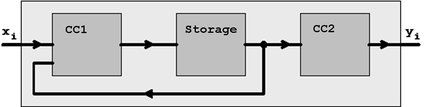
Figure 6.8: Moore Machine
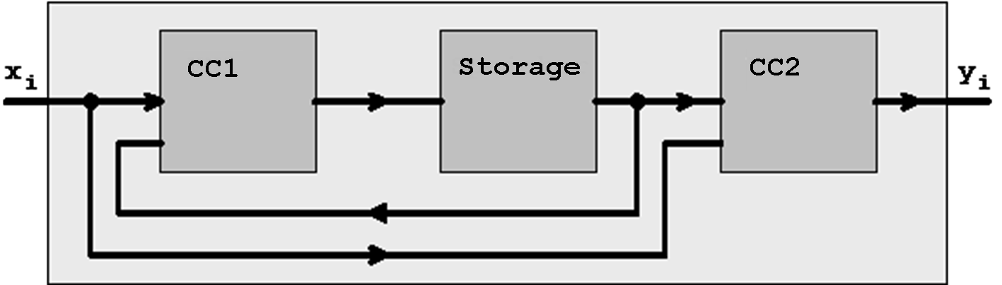
Figure 6.9: Mealy Machine
As has been shown before, it is possible to implement logical functions using storage devices. In this process the truth table (function tablle) of the Boolean Function that should be presented will be directly deployed in the storage element.
Obviously an FSM can be implemented in similar form, replacing the combinational circuit CC that is responsible for the logical function using a storage realization.
For this application the storage should be configured as a RAM storage device (random access memory), i.e. random access of the individual memory cells (locations) should be possible. Thus each single memory location can be activated using a unique address, and the content of the storage becomes accessible.
| Figure 6.10: Storage Organization | 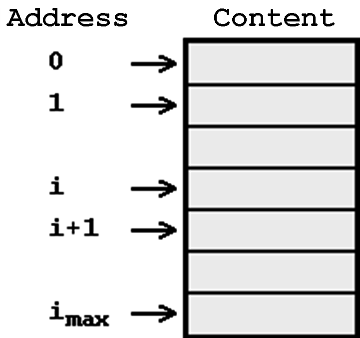 |
Example:
A storage unit built up with 32 storage cells, that can store two bits at each location (address):
|
|
| |||||
Table 6.2: Definition of the Storage Cells.
In order to realize a Boolean Function in a storage, the function arguments are now interpreted as memory addresses. The corresponding function value represents the content of the memory cell.
In the case of a function with n arguments a total of 2n storage cells will be necessary. For each storage cell an information width of one bit is required (for each combination of arguments the function value can only be '0' or '1' ).
In case that several functions (that depend on the same arguments) should be realized in memory, for each individual function an information width of one bit will be necessary.
Example:
Two functions f(a,b,c,d,e) and g(a,b,c,d,e) should be realized together in one storage unit. Consequently the total capacity of the storage will be 32 * 2 storage cells (bits):
| Table 6.3: Storage Realization of two Functions. |
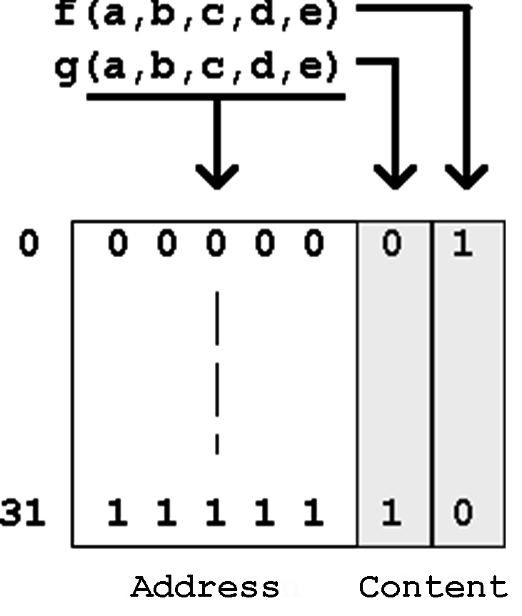 |
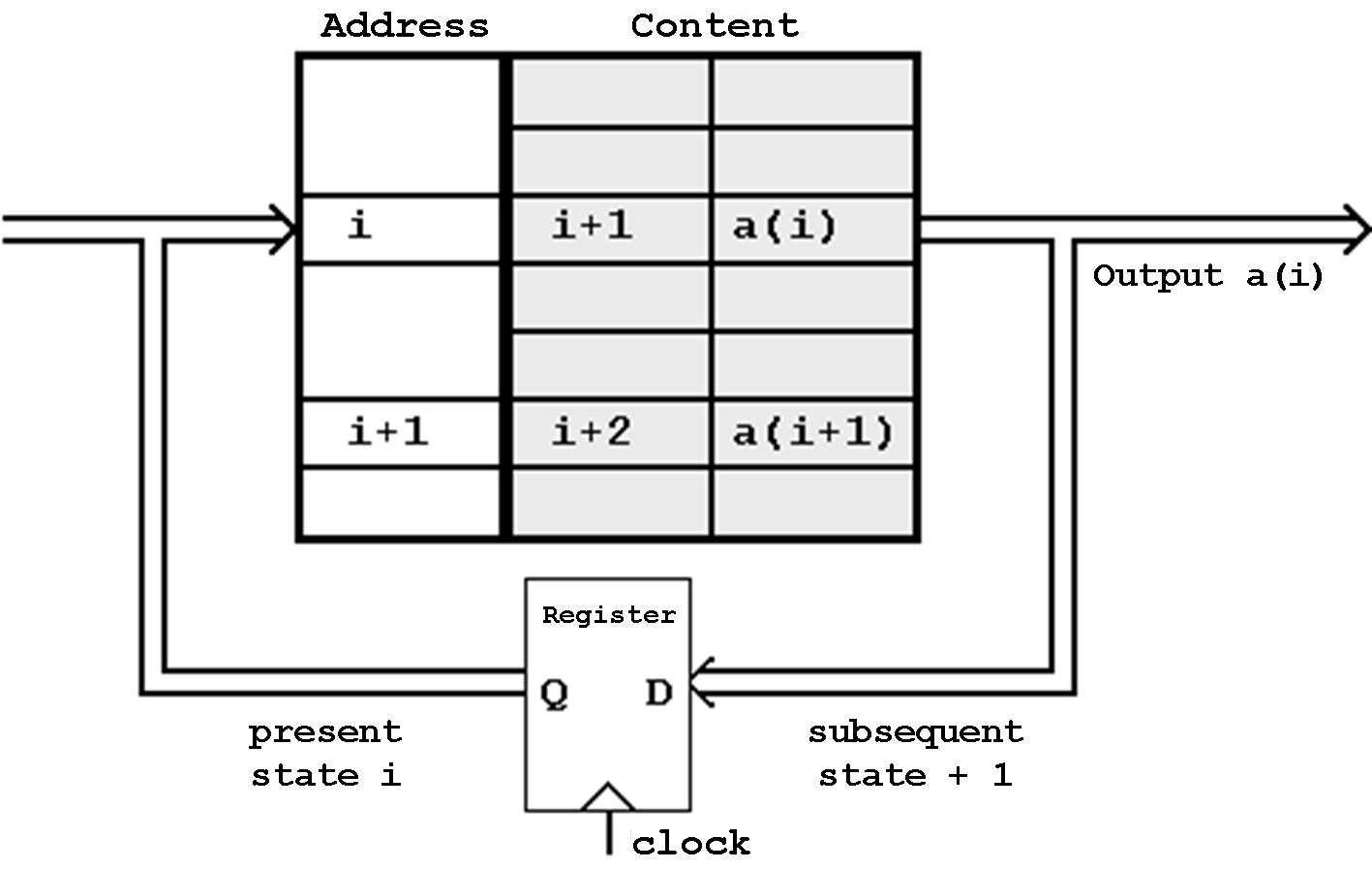
Figure 6.11: Storage Realization of a Finite State Machine (Automaton).
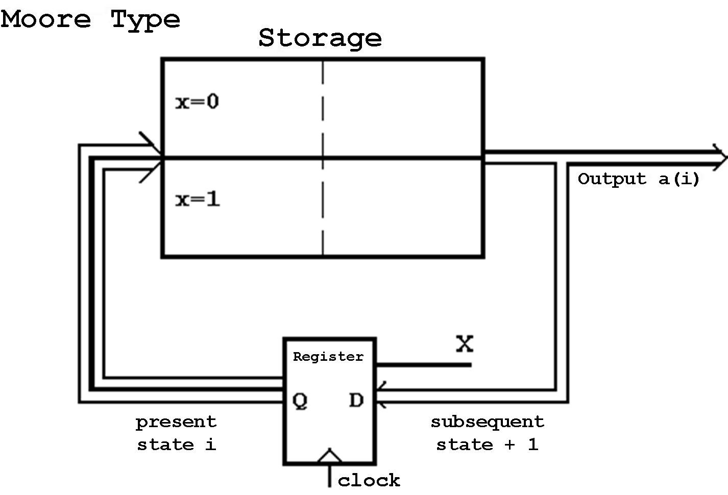
Abb. 6.12: Storage Realization of a Moore Machine.
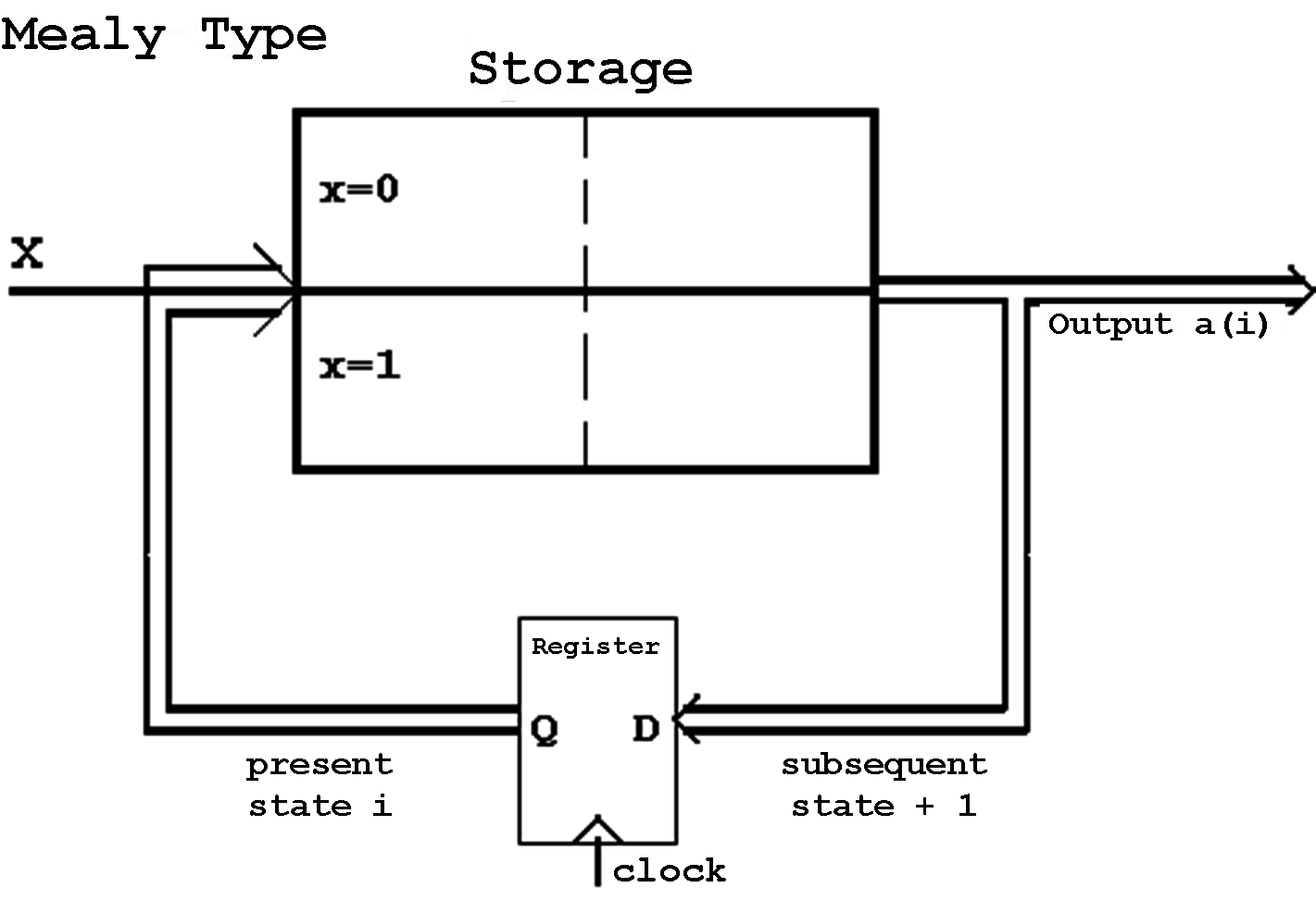
Abb. 6.13: Storage Realization of a Mealy Machine.
An important application of storage-based FSMs is the implementation of microprogrammed FSMs for the instruction control in modern microprocessors.
In this case a given microprocessor instrunction is disassembled into a series of so-called microinstructions. The corresponding sequence (the microcode) will be stored in a microprogram memory (storage).
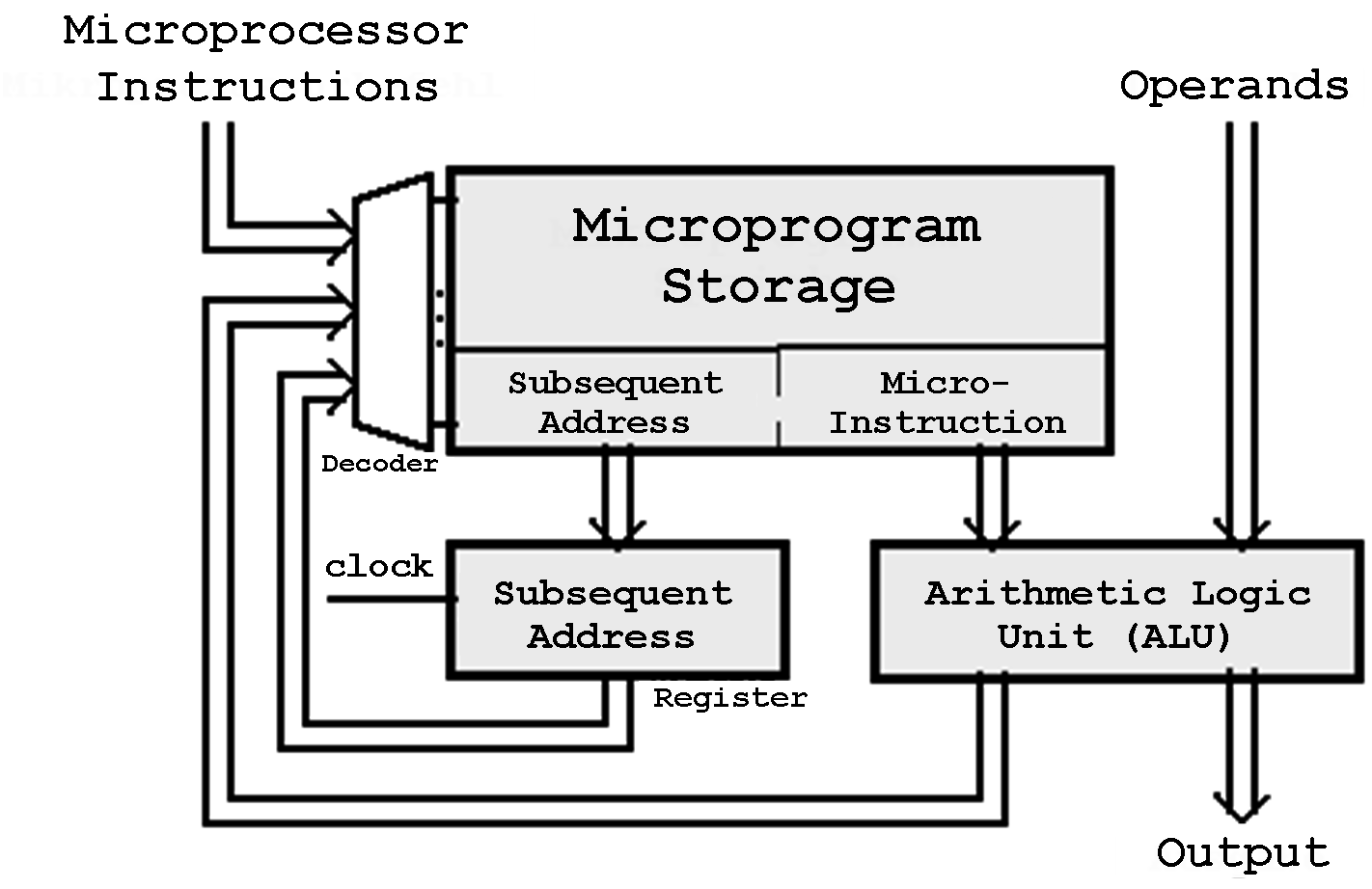
Figure 6.14: Structure of a Microprogram FSM
| Contents | Previous Chapter | Next Chapter |