1 Boolean Algebra and Digital Logic
1.8 Summary
Circuit Symbols according to ANSI/IEEE Std 91a-1991 (IEEE Standard Graphic Symbols for Logic Functions)
The following table summarizes the most important circuit symbols as defined by the IEC/ANSI/IEEE standards.
| Symbol
|
Description
|
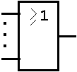 |
OR Element
The output stands at its 1-state if and only if one or more of the inputs stand at their 1-states.
|
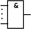 |
AND Element
The output stands at its 1-state if and only if all inputs stand at their 1-states.
|
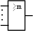 |
Logic Threshold Element
The output stands at its 1-state if and only if the number of inputs that stand at their 1-states is equal to or greater than the number in the qualifying symbol, represented here by m.
NOTE 1: m shall always be smaller than the number of inputs.
NOTE 2: an element with m=1 is equivalent to an OR element.
|
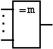 |
m and only m Element
The output stands at its 1-state if and only if the number of inputs that stand at their 1-state is equal to the number in the qualifying symbol, represented here by m.
NOTE 1: m shall always be smaller than the number of inputs.
NOTE 2: an element with two inputs and m=1 is an exclusive-OR element.
|
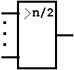 |
Majority Element
The output stands at its 1-state if and only if the majority of the inputs stand at their 1-states.
|
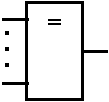 |
Logic Identity Element
The output stands at its 1-state if and only if all inputs stand at the same state.
|
Table 1.9: Standard Graphic Symbols for Logic Functions.
| Symbol
|
Description
|
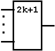 |
Addition-mod-2-Element
(ODD element, ODD-parity element, addition modulo 2 element)
The output stands at its 1-state if and only if the number of inputs that stand at their 1-state is odd (1, 3, 5, etc.).
|
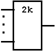 |
EVEN Element, EVEN-parity Element
The output stands at its 1-state if and only if the number of inputs that stand at their 1-states is even (0, 2, 4, etc.).
|
 |
Buffer without specially amplified output
The output stands at its 1-state if and only if the input stands at its 1-state.
|
 |
Negator, Inverter (in the case of device representation using a
single logic convention)
The output stands at its external 0-state if and only if the input stands at its external 1-state.
|
 |
Inverter (in the case of device representation using direct polarity indication)
The output stands at its L-level if and only if the input stands at its H-level. |
Table 1.10:
Standard Graphic Symbols for Logic Functions (continuation).
The Inverter symbol shows that attributes can be added to inputs, outputs and other connections, in order to show a logic negation or polarity, respectively:
Table 1.11: Negation, polarity, and dynamic input symbols.


