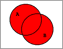
Figure 1.14: Venn-Diagram of the OR-Function.
| Contents | Previous Chapter | Next Chapter |
In the group of Boolean functions with n = 1 and n = 2 the functions AND, OR, and NOT play a dominant role. Therefore their properties will be discussed here in more detail:
1.5.1 The Boolean Function "OR"
The OR-Function corresponds in set theory to the set union or the function "Disjunction".
The set union
A ˅ B or A + B
describes the set that contains all the elements of the individual sets A and B. Again this can be shown graphically using a Venn-Diagram.

Figure 1.14: Venn-Diagram of the OR-Function.
Assuming that the Venn-circle includes - as defined before - the argument value "1", then the logical operation a + b will have the result "1" exactly when at least one argument has the value "1".
Obviously this union of areas corresponds to the function
As indicated before in digital design an expansion to n > 2 is done, without modification of the basic operation of the Boolean function itself.
Therefore the following is valid for the n-fold OR-Function:
or (with the same significance)
This situation can also be shown in an expanded truth table for n arguments:
| <- characterizes the Boolean function "OR" | |||||
In a similar approach the circuit symbol of the n-fold OR-Function is derived from the binary OR:
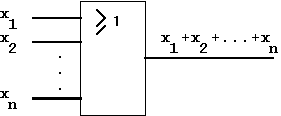
Figure 1.15: Circuit Symbol for the OR-Function (according to IEC)
Referring to the technical realization of this circuit function it is also called "OR-Gate".
The AND-Function corresponds in set theory to the set intersection (or cut set) or the function "Conjunction".
The cut set
corresponds to the set that contains those elements that are part of the individual set A as well as the set B. Again this can be shown graphically using a Venn-Diagram:
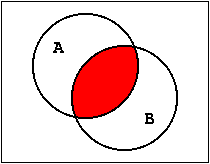
Figure 1.16: Venn-Diagram of the AND-Function.
Accordingly the logical operation a·b will have the result "1" exactly when both arguments have the value "1".
This overlap of areas obviously corresponds to the function
The transition to the n-fold AND-function results accordingly in:
or (with the same significance)
Again this situation can be shown in an expanded truth table for n arguments::
| <- characterizes the Boolean Function "AND" |
In a similar approach the circuit symbol of the n-fold AND-Function is derived from the binary AND:
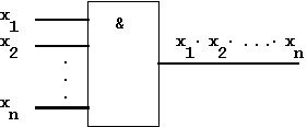
Figure 1.17: Circuit Symbol for the AND-Function (according to IEC)
Referring to the technical realization of this circuit function it is also called "AND-Gate".
1.5.3 The Boolean Function"NOT"
The Boolean function "NOT" (Negation, Inverse) has already been introduced and interpreted in Chapter 1.3.
The NOT-Function corresponds in set theory to the complement set or the complement function, respectively..
Table 1.8: Truth Table of the NOT-Function
This function presents a simply unary operation. An expansion to n arguments is not meaningful. But in connection with the n-fold functions AND and OR this function plays a very important role in circuit design (see below).
In a widened meaning the term of an inverse function can be introduced:
Definition:
Two Boolean functions f(x1,x2,...,xn)
and g(x1,x2,...,xn)
are inverse to each other, when the following is valid for all n-tuple (x1,x2,...,xn):
 |
(1.4), |
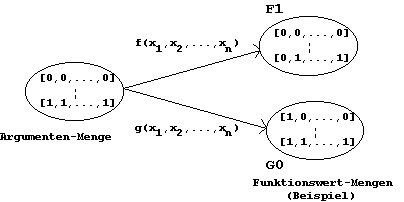
Figure 1.18: Inverse Boolean Functions.
| Contents | Previous Chapter | Next Chapter |