 |
 |
Team TWO©
|
|
|
Mobile Robots This is the official Mobile Robots Homepage of the Team TWO©.
The Page is part of an elective project during our studies.(Best viewed with 800x600)
 |
 |
|
|
|
|
 |
 |
 |
| - Analog IR Sensor Analyzing | - Project Management | - IR- Transmitter Design |
| - C- Programming | - Straight On Driving | - The Headlight Development |
| - Documentation | - Online Documentation
Homepage |
- Top Sensor Layout Design |
| - The Top Sensor Man | - C- Programming | - Documentation |
| - Top Sensor Layout Design | - The Ground Sensor Man | - Transmitter Modell |
|
|
|
|
 |
 |
 |
| - C- Programming | - Documentation | - C- Programming |
| - Documentation | - C- Programming | - Documentation |
| - Top Sensor Layout
Prototype Manufacturing |
- Product Placement | - Software Development |
The project is an elective
course at the University of Applied
Science Kiel, Germany.
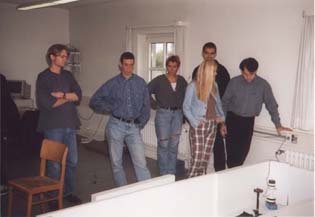
This was the first course about mobile robots. Causes of this there
were a lot of challenges.
The first was to get the base robots from a company in the USA called
Mekatronix(tm).
The robots wait three weeks at the German customs duty.
But Prof.
Dr. Dispert, one of the instructors, was able to free the robots.
After that we rearmed the robot with our special
equipment.
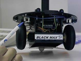
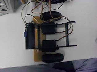
The base robot is a kit; a lot of parts are from radio controlled model
cars and planes. For example, the drive engines are standard model servos
and the tires came from a RC airplane.
The heart of the robot is a two layer computer board with a Motorola(tm)
68 000 processor.
We program the robot in 'standard C '. There is also a meta language
available, called "PROGO", but this language is not powerful enough .
The inventor of PROGO(tm) is the company Mekatronix(tm).
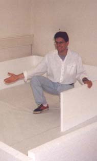
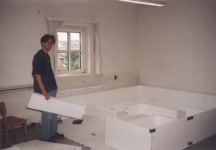
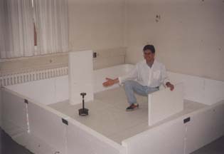
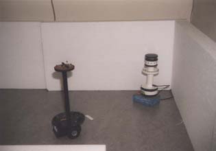
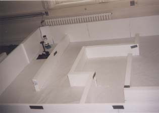
The Robot had to find an IR- Emitter in the labyrinth.
It is not allowed to touch any wall. The Robot had to stop in front of
the Emitter and to signal, that he arrived. Perhaps in the future the other
Robots are ready, so we can make a championship with other teams.
|
|
|
 |
 |
|
|
|
 |
 |
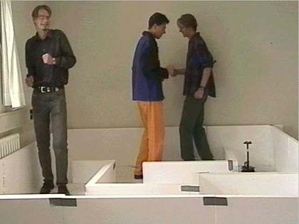
Because no other team finished their robots at the end of the term,
we just made a race:
Human being against our intelligent Robot. You can see the robot in
bottom corner on the right.
There is also a ![]() VIDEO available (QuickTime(tm) Plug in or MS(tm) Media Player 2(tm)
necessary).
VIDEO available (QuickTime(tm) Plug in or MS(tm) Media Player 2(tm)
necessary).
Click here to go to the download area.
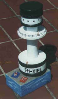
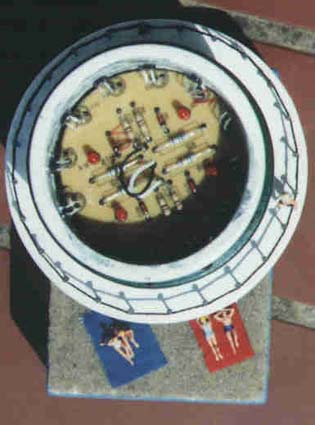
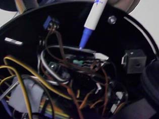
Here is the IR- Transmitter, it is an original model of a "Leuchtturm"
 |
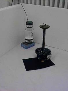 |
| Here is the original model of the ir- light emitter. | The Robot stops, if he arrived on a back surface. |
1.1 Headlight- Rules
(Taken from Un.Aveiro - Electronics Department, May
1998)
1.1.1 Goal area:
The headlight identifies the Goal area. The Goal area
is a circle with a 50cm radius, painted in black. The headlight is at the
center of the goal area.
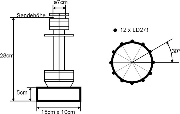
1.1.2 Dimensions:
The headlight is 27cm to 29cm high. It stands on a
rectangular base 10cm width, 15cm long and 5cm high.
1.1.3 Radiation:
The headlight radiate Infra-Red light, modulated at
25kHz. There are 12 leds in the headlight (MLED81 or equivalent), equally
spaced on a 7cm diameter circle.
2 Realization:
2.1 Schematic:
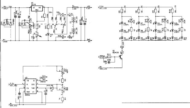
2.2 Functional description:
The schematic is divided into the following three
units:
2.2.1 The power unit:
The headlight works with a battery pack or a wired
power connection. These two current circles are separated with the relay
(V23042). That means if you use the wired power connection the battery
pack is disabled.
2.2.1.1 If you use the battery pack the current just runs through the fuse into the oscillation and the sending unit.
2.2.1.2 If you use the wired power connection the input voltage will be fixed down to 7.2V. This is realized with the regulator LM317. You can adjust the voltage with the poti R7 but it should be the same voltage as the battery pack. The input voltage can be from 10V/DC to 23V/DC so that you can use a number of different voltage sources. The two diodes at the input of the voltage unit are just for safety if you change the positive and negative power cables.
2.2.2 The oscillation unit:
The oscillation unit is an standard application of
the NE555- oscillator IC. There is to mention that you need the Diode D1
because the impulse time and the pause time of the sending signal should
have the same time (20µs+20µs=40µs= 1/25kHz).
You can adjust the pause time with the poti ROFF and
the impulse time with the poti RON.
On the output (pin 3) of the NE555 you can measure
the rectangular sending signal, which is wired to the base of the switching
transistor of the sending unit.
2.2.3 The sending unit
Die IR- diode matrix of the sending unit is made of
three IR-diodes in serial (e.g. D2 D3 D4) which are parallel to other three
IR-diode in serial (e.g. D7 D8 D9) and that four times. We had to do it
that way because we used the IR-diode LD271 with a forward voltage of 1.9V.
We are unable to put more than three diodes in serial because our power
unit gives a voltage just about 7.2V.
The switching transistor Q1 switches the IR-Diodes
in time of the oscillator unit. The parts R14 and C4 are just to speed
up the Transistor. The resistors R5 R8 R9 R10 are for regulating the IR
diodes current to 250mA. That sounds much but if you take a look into the
datasheet of the LD271 you will see that you can pass a forward current
up to 310mA if you had an interrupted source voltage like ours.
The announcing diodes (D8 D10 D14 D18) will emit light,
if one of the IR-diodes has a defect. If an IR-Diode has a defect there
will be a high resistance that means a high voltage. Because of that high
voltage the Z-Diodes (D6 D19 D20 D21) will let the reverse current get
through and the announcing diodes will spend light.
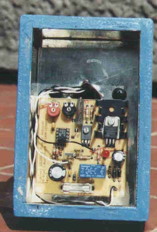
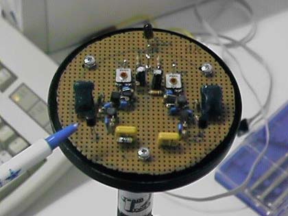
Testboard:
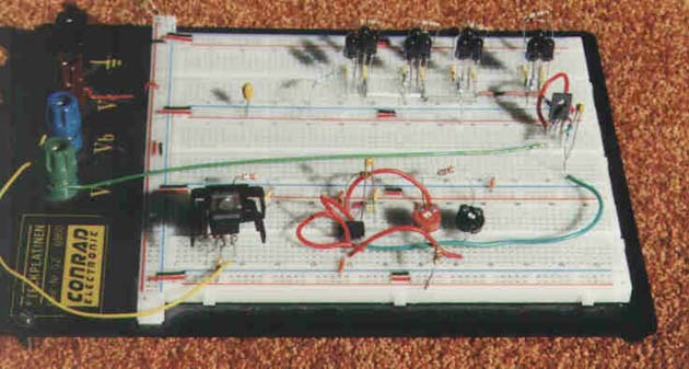
3. Layout:
We shared the whole schematic into two units for the
layout.
The voltage unit and the oscillator unit at the bottom
section of the housing. The sending unit at the top of the housing. This
got it's advantage because we save a lot of work to wire the sending unit
that means that there are just two wires.
|
|
|
 |
 |
4. Measurement:
We measured the voltage at R5 with an oscilloscope.
Because R5 is an 10 Ohm resistor we can calculate the current that runs
through R5 with the Ohms Law. The current through R5 is the current through
the IR diodes that means the sending current.
The measurement of the sending current was in DC-
connection with 1V/Div
|
|
|
 |
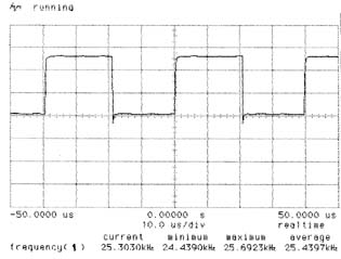 |
As you can see, we measured a sending current of 250mA
Hint: If you work with the wired power opportunity
you have to measure with an earth free oscilloscope.
5. Receiver:
The receiving diode of the LD271 is the SFH205F
So that the Robot can find the IR- Emitter, he have two high sensitive IR- detectors.
To download the layout and the part list click here to go to the download area.
One problem is the straight on driving. The robot has two drives. If
both drives turn with the same rate, the robot drive straight on. Cause
of the chassis hardware design, the servos has to turn in contradiction
direction, to drive forward or backward. The servos have very cheap hammer
brushes, so that they have different turns per second in each direction.
Ok so long, but the engines have a non-linear behavior. One way to drive
on straight is to measure the rotation per minute and program a controller.
But we do not have hardware to measure rotation. So we found out a very
easy and cheap way to drive on straight. We just try out. We do this with
different speeds.
The only problem we have is that the battery voltage is not constant.
This is the fact for our solution. We just use a voltage regulation circuit.
 |
 |
|
|
|
We program the robot in standard C; the functions for direct hardware access are supported by Mekatronix(tm). Cause we made a competition, there is now only a part of the source code available. Sorry, but you must understand that. We spend a lot of time to program. Ok you can get a little example , download the source code of the example or all executable files.
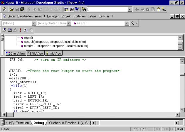
The function turn(...) lets the robot spin around its axis until the tower is directly in the straight-ahead-position
void turn(int k, int speedr, int speedl, int uirdl, int uirdr)
{
/* the following do-while statement defines the variable k which is
non-zero if */
/* the tower is not straight ahead from the robots upper IR's. */
/* while spinning into the straight-ahead-position, k gets smaller
*/
/* when it reaches a tolerance value smaller than 4, the robots' turn
is finished */
do
{
uirdr = UPPER_RIGHT_IR;
uirdl = UPPER_LEFT_IR;
if (uirdr > uirdl)
{
speedl = SLOW_SPEED_L;
speedr = ZERO_SPEED;
k=uirdr-uirdl;
}
else
{
speedl = ZERO_SPEED;
speedr = SLOW_SPEED_R;
k=uirdl-uirdr;
}
wait(200);
/* wait for hardware delay*/
if (k<4) k=0;
motorp(RIGHT_MOTOR, speedr);
motorp(LEFT_MOTOR, speedl);
} while (k);
motorp(LEFT_MOTOR,
ZERO_SPEED);
motorp(RIGHT_MOTOR,
ZERO_SPEED); /* stop the robots' spinning
*/
wait(1000);
/* wait for hardware delay */
}
To download the example click
here to go
to the download area.
|
|
|
 |
 |
|
|
|
 |
 |
Download Area Click here to start downloading the example function: "turn".
Click here to start downloading the final layout and part list.

Select the video format to start downloading the VIDEO
(249KB).
Intel Indeo(tm) Codec R4.1 or higher required.
- Video for Apple(tm) QuickTime(tm) or Browser QuickTime(tm) Plugin: VIDEO.MOV
- Video for Microsoft(tm) Media Player2(tm): VIDEO.MPGPlease chose the executable files you need:
- A program to drive trough a channel.
- A program to stop in front of an obstacle.
- A program to avoid, if an obstacle is attached.
- The final race program to find an IR- Emitter in a labyrinth.
Here are the final source codes for all programs:
(Restricted access, for instructors only, password required.)
Link Area Interactive Manuals:
Manuals (PDF-files):Sharp-Manuals (Links, PDF-files):
- PROGO Applications Manual for the TJ Pro Robot
- PROGO Language Reference Manual
- TJ Pro Education Manual Using IC
- Reinforcement Learning on a TJ Pro
- Sensors for Remote Control (Sharp U.S.A.)
- Data for IR Detecting Units
- GP1U58X Series, IR Detecting Unit for Remote Control
- GP1U58Y Series, IR Detecting Unit for Remote Control
IS1U621/IS1U621L, IR Detecting Unit for Remote Control
Why Do We Enjoy This Project ?
Cause it is a good combination of hardware and software development.
See it on your own:
 |
 |
 |
Any comments or questions ? Send a mail to: team-two@gmx.de ![]()
Parts of this are based on the work of the Independent Team TWO© Group.
Team TWO FH-KIEL Operation Research Development
Copyright 2000 ST-Software Coperation©
The Team TWO© logo is copyright by the
Independent Team TWO© Group.
This page is a final release.: v.0.6a
Date Code: 17:15PM/8/22/2000
![]()
But nevertheless
This Page is always

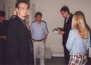
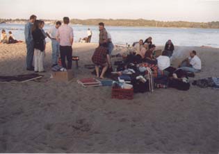
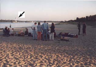
Here a few pictures from our last student beach party.
|
|
|
 |
 |
FH-Kiel
Team Computers
ST-Software Corporation
Team TWO Group Inc.