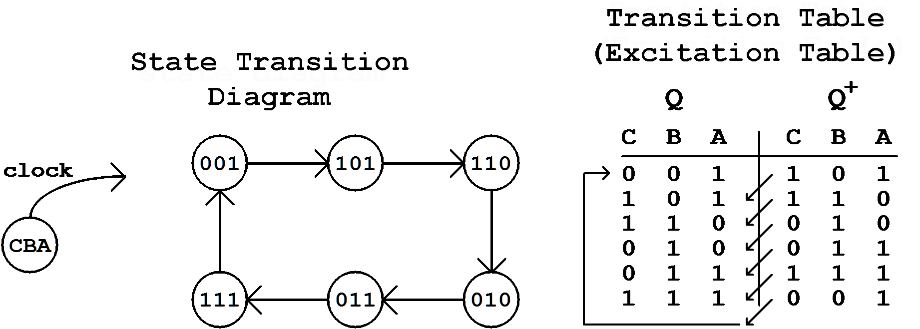
Figure 7.1: State Transition Diagram and transition Table.
| Contents | Previous Chapter | Next Chapter |
The behaviour of these counters will be described using the state transition diagrams that are already known from the finite state machines.
Figure 7.1: State Transition Diagram and transition Table.
In this simple example the state transitions are triggered by the active edge of a clock signal.
When during a state transition the bits of the state coding are changing exactly at the same time, the circuit is called (clock)synchronous . When however the single changes are triggered in a time-delayed form, this principle can be called quasi-synchronous. Thus the distinction from the clock-free asynchronous FSMs is also possible.
The pulse that is supposed to be counted is normally the clock input signal of the finite state machine.
In synchronous operation of the counter this clock signal triggers all flip-flops simultaneously with each change of state. This happens even when the state coding is not requiring a change of the flip-flop output.
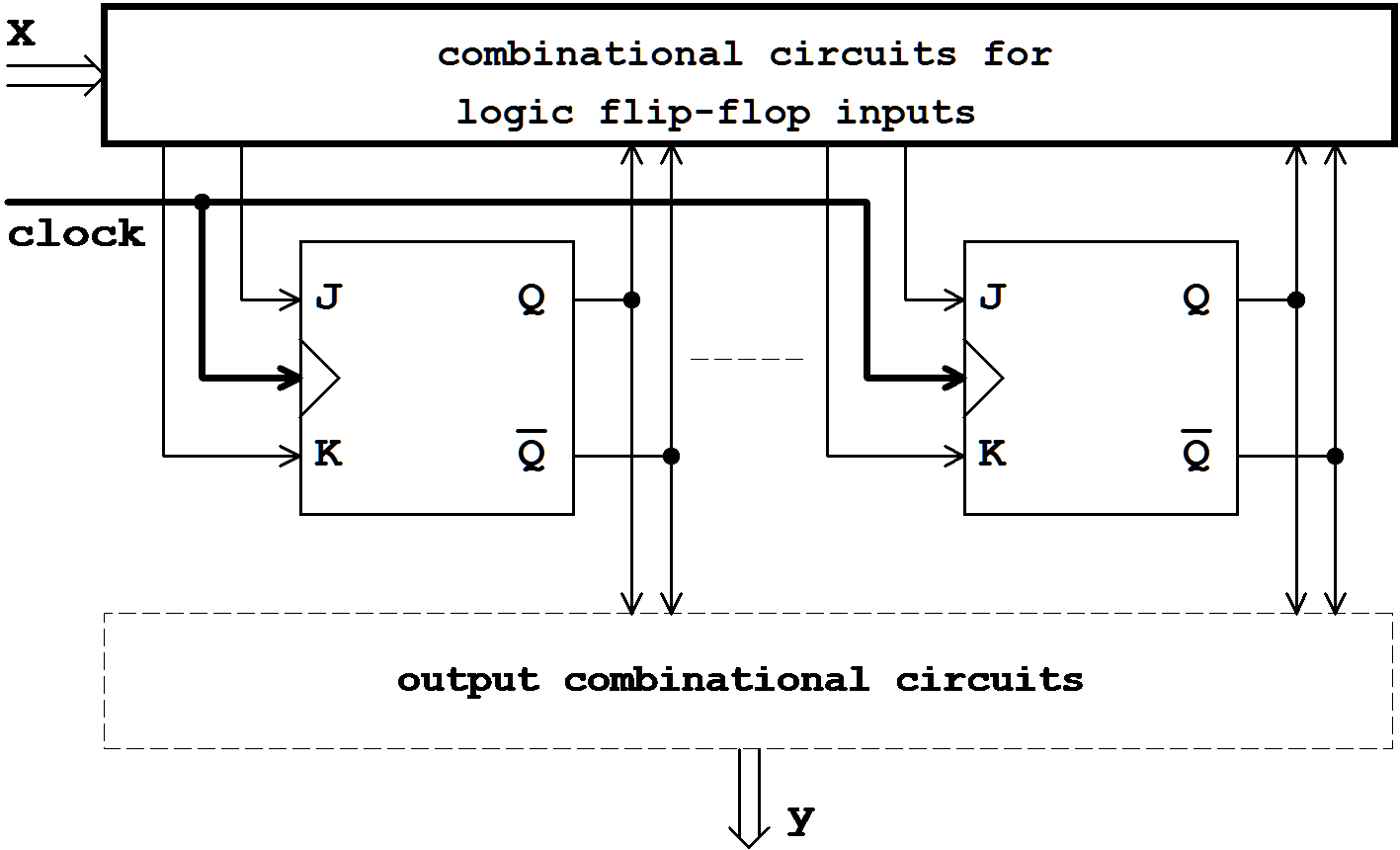
Figure 7.2: Synchronous Counter.
Contrary to this the triggering of the flip-flops can be suppressed in asynchronous operation, in case that for a change of the state the bit change is not required.
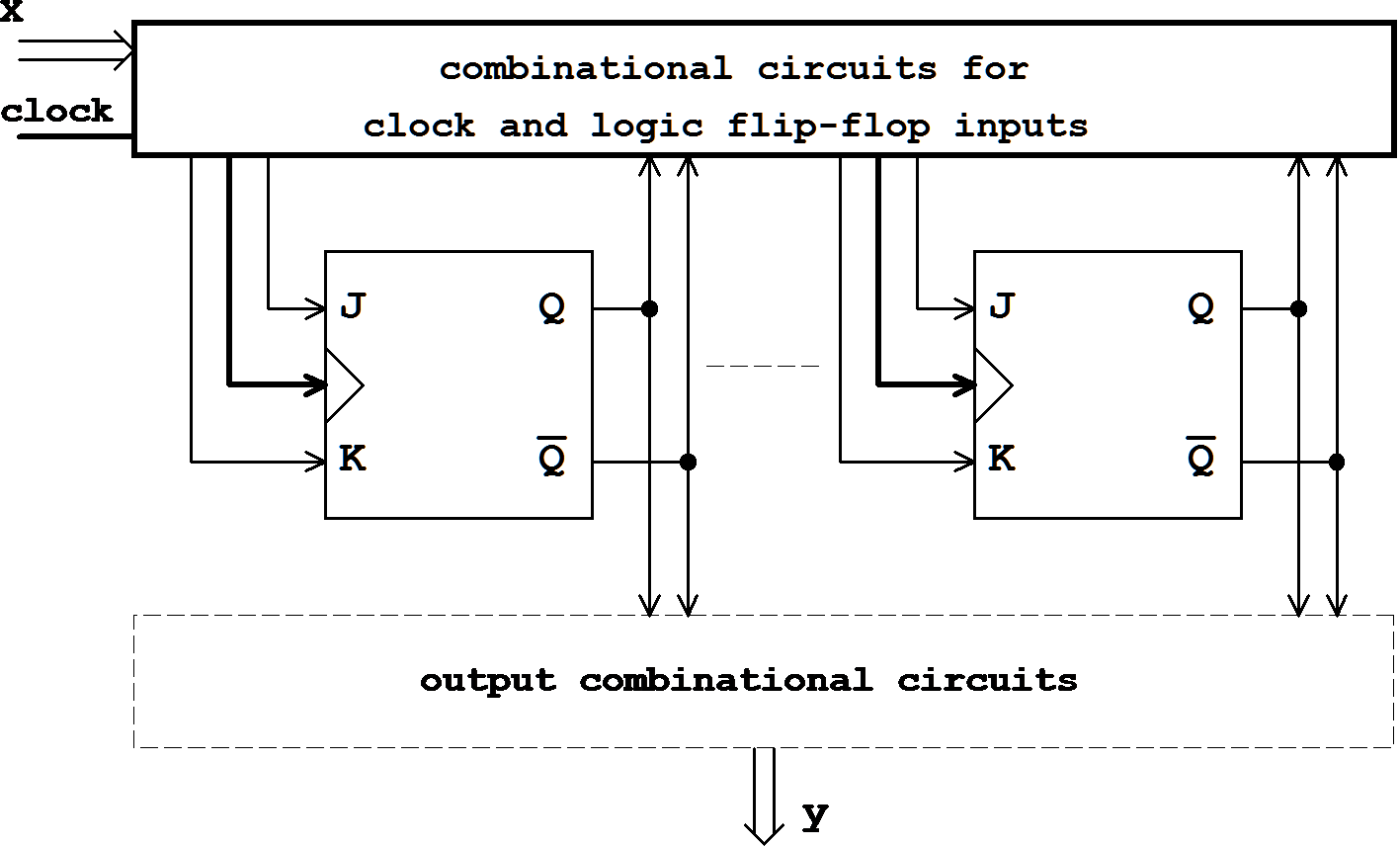
Figure 7.3: Asynchronous Counter.
This form of not-triggering is the easiest form of storing values. But this does not introduce asynchronicity of the counter behaviour yet. Only with another form of simplification this will be the case:
In the combinational circuit for the flip-flop triggering the change at the FF output will be used to trigger another FF. With this bit change the "serial" procedure can continue, triggering in turn the following flip-flop.
Thus the state change in an asynchronous counter will be performed through a successive bit change of the state code, called ripple changing, so that in the controlling combinational circuit occasionally old and already changed values of the FF outputs coexist.
In summary the different counter types can be characterized as follows:
Initially the combinational circuit for the output is optional, it is used only to convert the code from the state coding to the required output coding. For the design phase this separation in state coding and output coding offers an advantage: a more simple coding of the states can be achieved, in which the number of bit changes that occur as a consequence of the state change can be minimized.
The input variables of a counter are defined according to the intended function. Therefore two signal groups can be distinguished.
For the realization of these functions at least one combinational circuit is required, that controls the logic inputs of the flip-flops and possibly the clock input.
In case that the counter output should not only depend on the current state (or even be identical with the state code) but also on the control signal X, another combinational circuit for the output cannot be avoided. In this network state code and input will be combined directly following the Mealy arrangement.
This combinational circuit can only be avoided in a counter that has been constructed following the Moore principle.
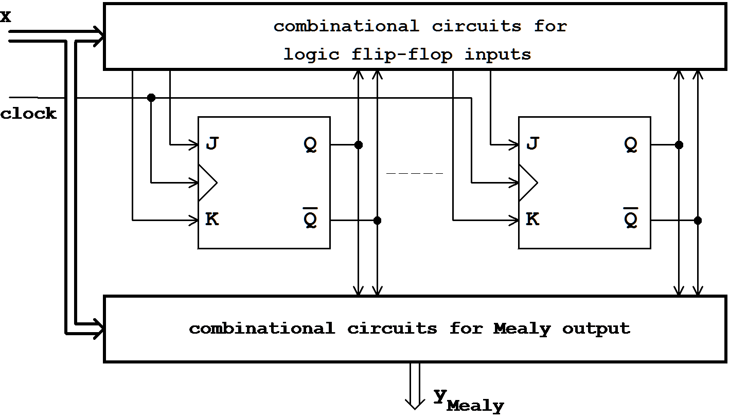
Figure 7.4: Synchronous Counter with Mealy Output.
However it should be observed that in a counter with Mealy output (see above) the glitches that may occur on the input lines X will have a direct effect on the output Y. In this case the buffer effect (produced by the flip-flops) is missing, that allows triggering at the exact time without any propagation of glitches.
| Contents | Previous Chapter | Next Chapter |